Importance:
- This manual is XY-R-12T type electrolytic weak acid water generator manual, including some XY-C general functions.
- In the manual, appropriate modifications such as graphics are simplified for convenience of explanation, and thus there is a possibility that the image does not match the actual image.The specific appearance is subject to the actual machine.
In order to make full use of this unit, please read and keep this instruction manual carefully to maintain the excellent performance of the machine and ensure long-term safe and correct maintenance. Thank you for your attention and support for this product.。
Ⅰ.Brief introduction
This product is the latest international sterilization equipment and Acid water machine. He is able to sterilize plants and neutralize alkaline soils. Conducive to the growth of crops..
The device has the advantages of simple operation, large output, low cost, wide adaptability and no pollution.
Technology, specifications and requirements
| Item | Technical Parameters | |
| Control System | Controller | High performance embedded industrial microprocessor |
| System resource | Various functions, multi-channel control | |
| Operation interface | One-touch operation display panel | |
| Main Specifications | Hypochlorous acid production rate | 500–12000L/h |
| pH | 3–4.5 | |
| Input voltage | AC three–phase 220V±10%,50Hz-60Hz | |
| Maximum power consumption | 8KW | |
| Working Type | Continue | |
| Size | Host
Pure water machine |
1400mm×800 mm×1500mm
1000mm×800 mm×1500mm |
| Weight | 300kg | |
| Technical requirements | working environment | Temperature 10-35 ° C, humidity below 80%, no strong electromagnetic interference around |
| Wiring | The regulated power supply is reliably grounded. | |
| Water supply condition | The input water quality meets national drinking tap water standard. |
Ⅱ.Host operation panel description
2.1 Main unit front: Figure 1
2.2 Side of the main unit: Figure 2
Waterway interface and component usage instructions
( Figure 1 , Figure 2 )
| Interface | Description |
| 1 | Mixed water tank,Electrolyzed water and tap water mixed |
| 2 | Additive inlet,Blending electrolyte injection port |
| 3 | Electrolytic power control,Electrolyzer operation switch and working status display |
| 4 | Touch Screen,Host operating system and working status display |
| 5 | Distribution box, host PLC program control system and electrical distribution system |
| 6 | RO Water Machine |
| 1 | Electrolyzed water outlet, output efficacy acid water |
| 2 | Overflow,Passage for each tank overflow |
| 3 | Inlet, continuous supply mixed electrolyte |
| 4 | Acid water outlet,Weak acid water by mixing electrolyzed water with tap water |
2.3 RO Control Panel Schematic: (Figure 3)

RO Waterway interface and component usage instructions: (Figure 3)
| Interface | Description |
| 1 | Program controller,Pure water machine program operation and working status display |
| 2 | Conductivity meter, conductive indicator display of pure water |
| Function indicator3 | Indicator 1 – power indicator |
| 3 | Indicator 2 – original water pump operation indication |
| 3 | Indicator light 3- booster pump running indication |
| 3 | Indicator 4 – Flushing indication |
| 3 | Indicator light 5 – low pressure indication |
| Operating knob 4 | Knob Switch 1-Automatic/Manual Conversion |
| 4 | Knob Switch 2 – Original water Pump Auto / Stop / Manual Conversion |
| 4 | Knob Switch 3-Booster Pump Auto/Stop/Manual Conversion |
| 4 | Knob Switch 4- Flush Valve Auto/Stop/Manual Conversion |
| 4 | Knob Switch 5-Emergency Stop/Reset Switch |
| 5 | Distribution box, RO water machine power distribution system |
| 6 | Pressure meter 1—Pre-filtration pressure |
| 7 | Pressure meter 2 – Post-filtration pressure |
| 8 | Pressure meter 3 – pre-film pressure |
| 9 | Flow meter 1-concentrated water flowmeter |
| 10 | Flow meter 2—pure water flow meter |
Ⅲ.The basic structure and composition of the machine
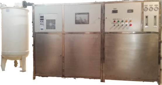
3.1The main structure of the machine comprises two parts of the main machine and the attached pure water preparation device.;
3.2The machine casing is made of stainless steel and has the advantages of anti-corrosion, rust prevention, hygiene and aesthetics. The panel is designed as a detachable panel for everyday maintenance; the back panel is integral with the frame。
3.3The electrical control system components inside the main unit are connected to the front operation panel and the display screen; the built-in cooling fan and the back panel are provided with vents. The waterway system inside the machine is equipped with a waterway detection and control system: the main components include metering pumps, electric working tanks, program-controlled solenoid valves, sensors, etc. The built-in liquid tank is detachable for easy daily maintenance。
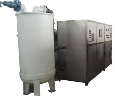
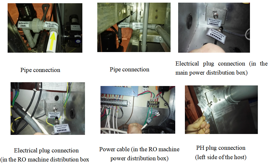
3.4For the convenience of transportation, the RO machine and the main machine are divided into two bodies. When installing, the two machines are put together, the water pipe parts are connected and screwed tightly, and the electrical plug-in connection is secure. See Figure 4;
Ⅳ.User preparation before installation
4.1 Equipped with household tap water and sewer.
4.2The indoor working environment temperature should be 5-35 ° C; and have good ventilation; indoor relative humidity should be no more than 60% during non-working period; have good lighting conditions; there is no strong electromagnetic interference source nearby.
4.3 There are three-phase AC 220V±10%, 50-60Hz, and more than 8KW load capacity. The power supply should be equipped with at least one 10A single-phase three-pin power socket. The grounding end of the socket must ensure good grounding; single-phase two-pin socket One. It should have a closed control switch and a three-phase air automatic protection switch of not less than 32A. One 32A single-phase air automatic protection switch.
4.4The room shall be provided with fixed tap water pipes and valves; the tap water source pressure shall be not less than 0.2-0.4 MPa; the room shall have floor drains or drain channels.
4.5The tap water quality should meet the drinking water hygiene standards stipulated by the state; when the tap water hardness exceeds the standard, special desalination equipment should be installed.
Ⅴ.RO machine water inlet conditions
This RO machine should be carried out under the following water inlet conditions. Pollution and damage not caused by this condition are not within the warranty of the system.
Minimum raw water pressure:40PSI (2.8Kg/cm2 )
Minimum water supply pressure flow:1.5T/H
Water temperature:18℃~30℃
PH range:4~9
Hardness:17mg/L(Based on CaCO3)
Turbidity:SDI<5
Total dissolved solids content:TDS<500 mg/L
And the raw water must meet the following requirements:
Iron:<0.1 mg/L
Free chlorine:Not checked out
Manganese:<0.05 mg/L
Organic matter:<1 mg/L
. Host installation
11.1 After opening the packing box, first check whether the parts are damaged during transportation, and check the parts and spare parts according to the list attached to the box. If any damage is found or does not match the list, it must be promptly delivered to the carrier. And shipper inquiry.
11.2 The water machine should be discharged reasonably in order. The left, right and rear plates of the machine should have a distance of more than 0.5m from the wall to facilitate ventilation, operation and routine maintenance.
11.3 Connect the water pipes according to the graphic interface provided in this manual.
11.4 If the tap water quality provided by the user meets the requirements of the host; connect the pipe fittings of the user’s indoor tap water to the main water inlet.。
11.5 The host pipe of the acid water outlet is connected with the water storage tank。
11.6 Connect the unit’s power cord to the user’s power air automatic protection switch. Check the grounding wire is good.